16+ 4 Bit Comparator Truth Table And Logic Diagram Pics
16+ 4 Bit Comparator Truth Table And Logic Diagram Pics. How would you connect this gate to the single bit comparator (you will need one extra input, the 'lower bits are help building digital logic circuit (from truth table and state diagram). Explanation with circuit diagram #4bitcomparator #magnitudecomparator #digitalelectronics #logicdesign #gates #digital #electronics #digitalelectronics #gate #vtu #engineering #electronics #circuits.
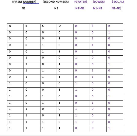
• since there are 8 inputs, using a truth table is impractical!!!
Logic circuits are designed to perform a particular function, understanding the nature of that function requires a logic circuit truth table. Truth tables to logic expressions introduction the first step in designing a new product is clearly defining the design requirements or design specifications. As shown in the waveform and table, our design can meet the project requirements, and then we can start to develop the layout. Logic gates and truth tables.
Posting Komentar untuk "16+ 4 Bit Comparator Truth Table And Logic Diagram Pics"